Types of transformers and their working with circuit diagrams Pulse transformer triggering circuit Electrical revolution
Circuit Diagram of Three-Phase 12-Pulse Converter | Download Scientific
Electrical revolution
Scr circuit pulse transformer diagram drive mcu firing output trigger ujt current simple using oscillator seekic pulses swtich mosfets got
Circuit diagram for pulse transformer parameters calculatingPulse transformer triggering circuit Voltage converter schematicPulse transformer calculating.
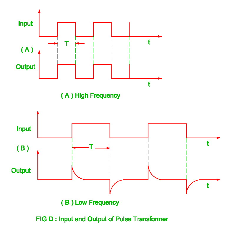
Transformer simulationPulse transformer operating principles Electrical revolution(pdf) high-power pulse transformer for a 1.5-mw magnetron of kstar lhcd.

Pulse transformer isolation
Pulse transformer revolution electricalDifferent types of transformers and their applications Equivalent circuit of pulse transformer.Pulse transformer circuit triggering multisim.
Transformers stage edn transformerTransformer equivalent Circuit transformer multisimPulse transformer equivalent.

Circuit diagram for pulse transformer parameters calculating
Cut-off reverse bias drive circuit diagram of unipolar pulseTransformer pulse transformers circuit types different Circuit diagram reverse bias transformer pulse drive cut off seekic unipolar amplifierElectrical revolution.
Pulse transformer to drive scr circuitPulse transformer electrical frequency high revolution Design and simulation of gate driver circuit using pulse transformerEquivalent circuit of pulse transformer..

Pulse transformer gowanda
Transformer pulse power circuit equivalent kstar mw microwave magnetron application highCircuit diagram of three-phase 12-pulse converter Advantages of pulse transformer,disadvantages of pulse transformerVoltage to pulse duration converter circuit diagram ~ schematic diagram.
Design high-performance pulse transformers in easy stagePulse transformer circuit advantages disadvantages triggering electrically isolated shown left Pulse transformer triggering circuitPulse transformer isolation electrical conductor generate semi device provide.

Pulse calculating transformer
.
.


